- Allergies and Air Pollution's Effect on Health
- Asthma & How it is affected by Air Pollution
- Air Pollution & Cancer
- Air Pollution's Harmful Effects on the Elderly
- More about HEPA and Carbon activated Filters
- Different types of air filters
- Mold Spores and Indoor Air Quality
- UV Air Purifier Guide
- What causes bad indoor air quality?
- How do Air Purifiers Work?
- Air Pollution May Cause Respiratory Infections
- Air Pollution in the workplace
- Pet Dander's Effect on Air Quality and Asthma
- Air Pollution & Sleep Apnea
- Top 5 Reasons Why you should purify Air
- What you need to know about indoor air
- How Pets cause allergies
- Tips on Choosing the Right Air Purifier
- Multiple Chemical Sensitivity
- What are Dust Mites?
- The History of Air Purifiers
- Air Pollution Problems of the new home
- 5 Ways to Reduce Your Pollen Allergies
- Sinusitis Causes and treatments
- What is HEPA filtration?
- Air purifiers and Wood Smoke
- Home Air purifiers and Cigarette Smoke
- Volatile Organic Compounds (VOCs)
- Formaldehyde Air Pollution
- Is your air purifier ozone free?

APEC Online Technical Guide 2
Make Sure the RO membrane is inserted correctly Two Common
Mistakes: 2) Insert Membrane into housing in the "wrong" direction. When you install the RO system, if you forget to put the membrane into its housing, or put it in the "wrong" (reversed) directon --> your water will not be filtered, and the RO will vibrate or make humming noise when you dispense water. How to check your RO membrane: Open up the membrane housing cap (remove Red tubing from cap) and look inside the housing. If you see a Black seal, then it's inserted correctly. See diagrams below.
Figure A: Correct way to insert Membrane
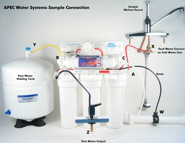
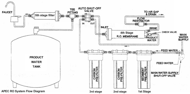
Figure B: System Connection Diagram Please refer to the diagram below to make sure that you have proper water line connections. There are 4 connections: Point A to X: Connect RO to COLD water supply - Red tubing. * Note: The Yellow tubing is a 2-way line. Product water enters and leaves the tank via this same line.
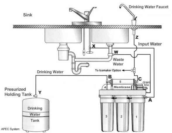
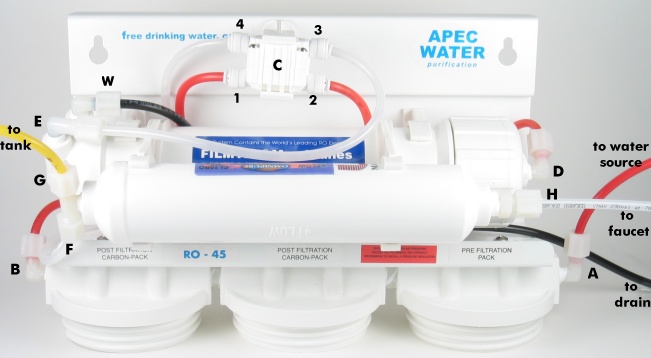
Figure C: System Troubleshooting Points Diagram The diagram below identifies testing points for troubleshooting procedures.
Troubleshoot Points Identification: Point A: Feed water inlet into Stage-1 filter Point B: Stage-3 filter's outlet port Point C: Automatic-Shut-Off (ASO) valve. For Permeate Pumped systems, the permeate pump replaces the ASO valve, it serves both as a pump and an auto-shut-off valve. Point D: Stage-4 Membrane housing inlet port. Feed water after passing the 3 prefilters enters the Membrane at this port. Point E: Check Valve. The filtered water from the Membrane passes through this Check Valve before it enters the storage tank. The Check Valve serves to block the water from back-flowing from the tank back into the membrane. Point F: T-fitting on the Stage-5 filter. This end of the T-fitting connects to the CLEAR pure water line. Point G: T-fitting on the Stage-5 filter. This other end of the T-fitting connects to the YELLOW pure water line which goes to the tank's valve. Point H: The output end of Stage-5 filter. Pure water leaves Stage-5 filter via this port, and flows onto the dispensing faucet.
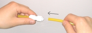
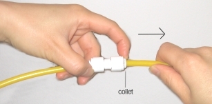
How To Use Quick-Connect FittingsBelow are samples of Quick-Connect type fittings on your RO systems. When connect tubing to these fittings, simply insert tubing into the fitting's ports. Please Do Not add "tube inserts" to these connections!
How To Connect & Remove Tubing:
System Flow Diagram
| |||||||||||